CarPi - Raspberry Pi with VW RNS2 DVD (MFD2)

Unfortunately the problem did not disappear after the work was done. At that time the
Volkswagen service station told me that the last option is a replacement of the complete
dashboard. It's price will be around 1000,- €. Because it can't be sent back,
I have to pay for it anyway. But it could be, that the problem will not be solved.
Round about that time the idea arose to scan the CAN bus with a Raspberry Pi to analyse
what's going on.
For a better understanding I devide the project in several pieces:
The MFD2 as a display for the Raspberry Pi

More difficult was the task to create the right VGA signals. To save money, my first try was
the Gert VGA 666 adapter.
(https://www.raspberrypi.org/forums/viewtopic.php?f=91&t=94424)
It took some time to realize that the Gert VGA 666 adapter is using an LCD output, which
supports progressiv only. But the MFD2 supports interlaced only. This will never match!
For the second try I used an HDMI VGA adaptor by manhattan.
(http://manhattan-products.com/hdmi-to-vga-converter3)
which I bought at a local store K&M COMPUTER. There was no audio ouput and the power supply by the HDMI plug of the Raspberry Pi was
sufficient to run the adaptor. In general I was able to create an interlaced VGA signal. A
first timing I found here:
(http://www.mp3car.com/forum/general/show-off-your-project/158651-oem-mfd2-vw-and-a-pc-my-next-ivi-to-replace-my-nexus-7-custom-hu)
Now the tough part began. Which timing and pixels would the MFD2 accept?
Well to make the long story short, the display has 400x230 pixel but the timing has to offer
800x460 pixel. Additionally the borders have to match the physical dots of the display.
How does this work?

At first the information of the adaptor has to be ignored. That thing knows only a few
settings that do not match the MFD2. To recognise this, took some time either. Therefore
the special mode has to be choosen, to set a proper timing. The Raspberry Pi will zoom the
given pixel and lines appropriate.
sudo nano /boot/config.txt# MFD2 at HDMI-VGA adapter
hdmi_ignore_edid=0xa5000080
hdmi_group=2
hdmi_mode=87
hdmi_timings 800 0 51 44 121 460 0 10 9 14 0 0 0 32 1 16000000 3
framebuffer_width=400
framebuffer_height=230
disable_overscan=1
... here it goes!
Because the Raspberry Pi will be mounted behind the dashboard I switched off all LEDs.
sudo nano /boot/config.txtdtparam=act_led_trigger=none
dtparam=act_led_activelow=off
dtparam=pwr_led_trigger=none
dtparam=pwr_led_activelow=off
Now the display should be always on. For that, some settings had to be changed too.
At first the screensaver had to be disabled at several locations.
sudo nano /etc/xdg/lxsession/LXDE-pi/autostart#@xscreensaver -no-splash
Next the mouse cursor should be invisable.
sudo apt install unclutter
sudo nano /etc/xdg/lxsession/LXDE/autostart#@xscreensaver -no-splash
@unclutter -idle 0.1 -root
And the power management had to be disabled.
nano ~/.config/lxsession/LXDE-pi/autostart#@xscreensaver -no-splash
@xset s noblank
@xset s off
@xset -dpms
The VSWITCH at the MFD2 should be switched by a infrared remote control. For that i installed
the normal lircd and configured the receiver. That I will describe at
another webpage.
For this description only the additional settings for the output are of interest. At first,
the GPIO pins have to be initialized. That's happening at the startup of the desktop:
nano ~/.config/autostart/poweron.desktop[Desktop Entry]
Name=PowerOn
Comment=Set GPIO
Exec=sh -c "sudo /home/pi/poweron.py"
Icon=/usr/share/pixmaps/python.xpm
Terminal=false
Type=Application
Categories=Application;
StartupNotify=true
Within the python script the GPIOs are configured.
nano ~/poweron.py#!/usr/bin/python
# RPi.GPIO Official Documentation
# http://sourceforge.net/p/raspberry-gpio-python/wiki/Home/
import RPi.GPIO as GPIO # import RPi.GPIO module
# Define Pins
AUX_ON_PIN=16
LIGHT_IN_PIN=20
MOTOR_IN_PIN=21
# choose BOARD or BCM
GPIO.setmode(GPIO.BCM) # BOARD for P1 pin numbering
# Set up In- and Outputs
GPIO.setup(AUX_ON_PIN, GPIO.OUT) # output
GPIO.setup(LIGHT_IN_PIN, GPIO.IN, pull_up_down=GPIO.PUD_UP) # input with pull-up
GPIO.setup(MOTOR_IN_PIN, GPIO.IN, pull_up_down=GPIO.PUD_UP) # input with pull-up
chmod +x ~/poweron.py
The reaction of the KEY_POWER is defined in lircrc :
sudo nano /etc/lirc/lircrcbegin
    button = KEY_POWER
    prog = irexec
    config = toggle_gpio 27
end
The program toggle_gpio switches the given output:
With this the configuration of the Raspberry Pi is finished and it may be mounted in the car.
sudo nano /usr/bin/toggle_gpio#!/bin/bash
if [ `gpio read $1` == 0 ]
then gpio write $1 1
else gpio write $1 0
fi
sudo chmod +x /usr/bin/toggle_gpio
Connecting the car

I like to use the video input while I'm driving. In a thread in the USA I found details
for the inputs of the MFD2.
(http://forums.vwvortex.com/showthread.php?2601216)
The VSWITCH input has to be connected to 12V via a 5k6 resistor to enable the video input.


Mounting the Pi


The side cover is fixed by clips only and can be removed easily. That is the way to get to
the Raspberry Pi when it is working.


Please be aware, to position the nose at first at the opening. Otherwise the clips will not be
in position or the cover can not be fixed.


Notice: Because of the guiding the upper clips have to be removed towards
the driver!
From my experience at minimum one clip will stick to the dachboard.
To bend the dashboard to thread the holes, some more screws have to be removed.
Unfortunately I did'nt take a picture of that.
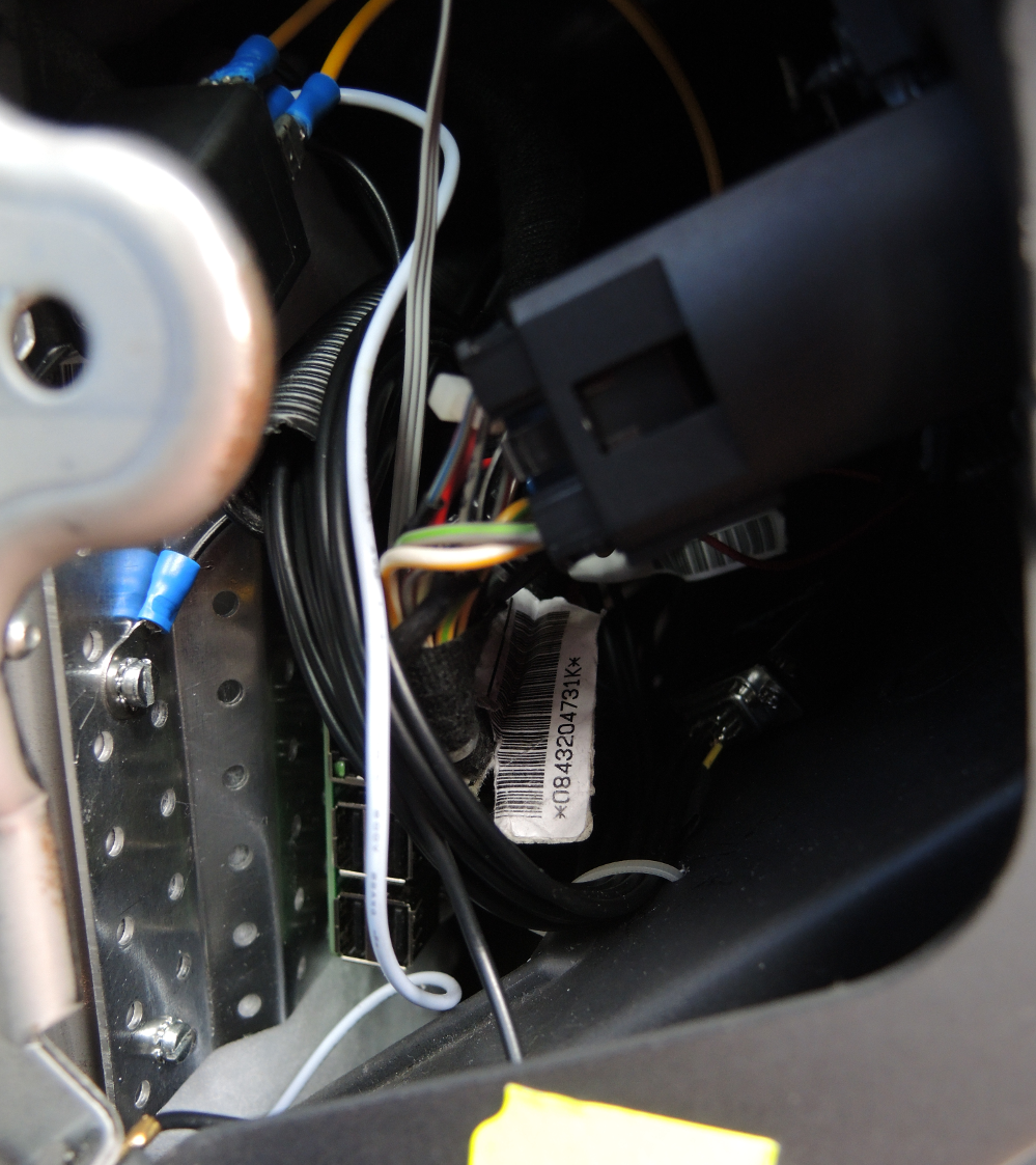


I bought the plug, combining two pieces, from VW too. I guess there is a cheaper way for this.

From left to right the signals are:
- Red
- Green
- Blue
- <NC>
- CSYNC
- <NC>
- Audio right
- Audio left
- <NC>

With the power button of the remote control (KEY_POWER), I activate / deactivate the VSWITCH
input of the MFD2. This offers two advantages:
- Even if the car is moving, the display can be used
- The audio input will stay connected. You can listen to the radio or the AUX-IN while the Raspberry Pi uses the display
So far this is the first part of the work.
Reading the CAN buses is about to follow ...
Reading the CAN buses is about to follow ...